Flexy
An open-source device for control education.
What is Flexy?
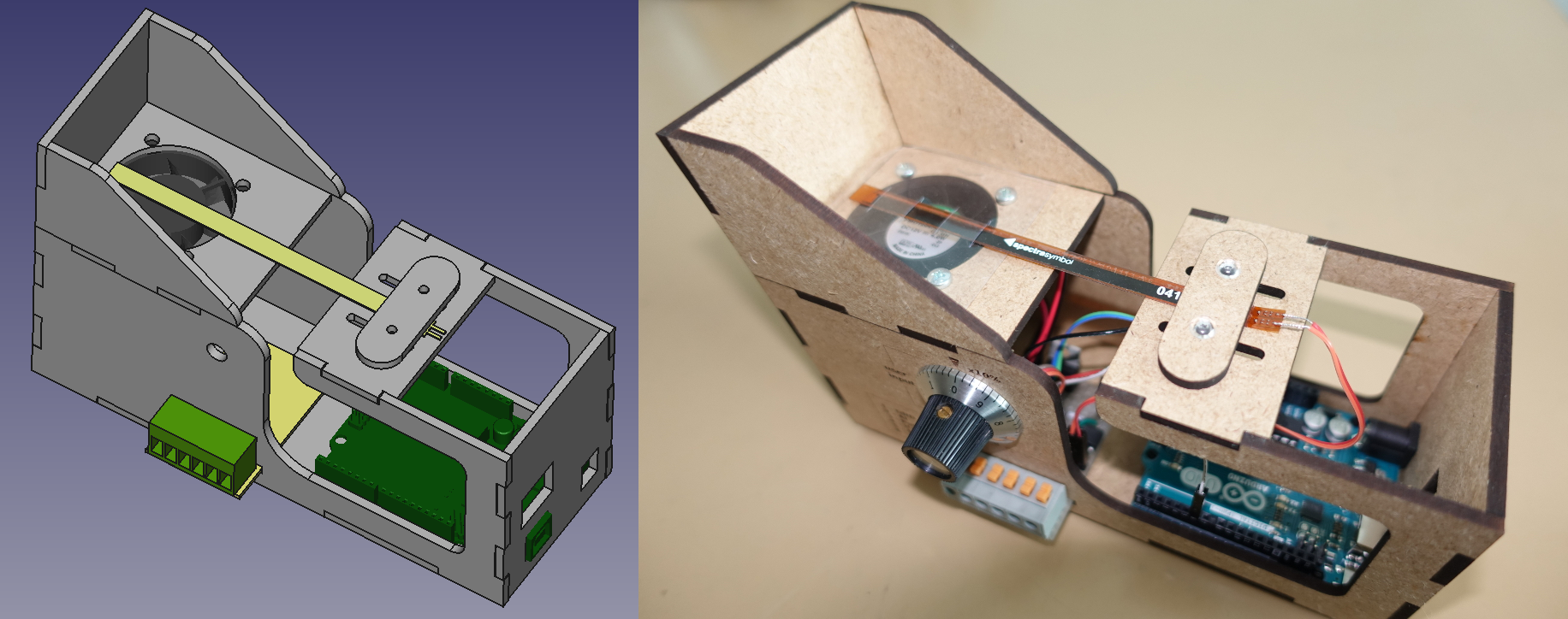
Flexy is an open-source hardware device for process control training and education. Flexy represents a simple dynamical system with one actuator (fan) and one sensor (flex resistor). The system allows to measure and control an air flow produced by fan. The air flows around an obstacle that is mounted on a flexible strip. Strip bends as a result of increased hydrodynamic pressure. The corresponding change in electric resistance of flex sensor is measured. Flexy is equipped with a microcontroller unit that allows to continuously control the fan speed and measure the bend of flex resistor. The dimensions of device allow to use standard short format Arduino type boards (Uno, Leonardo, 101, Zero, Yun, ...). Flexy is also equipped with one potentiometer knob as an additional input. User can define the functionality of knob in a program of the microcontroller (control setpoint, fan control, manual parameter change, ...).
Video (contains first prototype of device)
Flexy is made of laser-cut medium-density fibreboard (MDF). The dimensions of the device are 166mm/60mm/70mm (L/W/H). The device contains a small board with fan-control and sensor-conditioning circuitry. The fan requires an external 12V DC power supply.
Software
If equipped with Arduino-compatible board, the device can be programmed via Arduino IDE. The main library is contained within this repository. To download the files, use either git
git clone https://github.com/martin-kaluz/flexy-arduino.git master
A MATLAB API is also available. To install Flexy support for MATLAB, you can use either tbxmanager or direct download. Please note that MATLAB API is still in the development phase. Command line API (class Flexy.m) works in MATLAB versions R2009a and newer. The Simulink library was created in R2017a and may not work in old versions.
To install Flexy via tbxmanager, firstly install tbxmanager. Then run following command.
tbxmanager install flexy
MATLAB API works only if flexy_matlab.ino program is uploaded in Arduino board.
Electrical schematics
Flexy uses two simple circuits to control the motor of a fan and to sense the changes in resistance of a flex resistor.
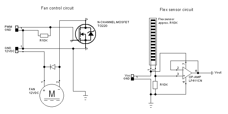
The motor control circuit uses a single N-channel MOSFET that energizes/de-energizes the motor's coil based on logical voltage state of PWM signal. The fan requires a 12VDC power supply to operate within its specifications. Flex sensor circuit is a simple impedance buffer for signal conditioning. A single operational amplifier LF411CN in a direct negative feedback configuration is used.
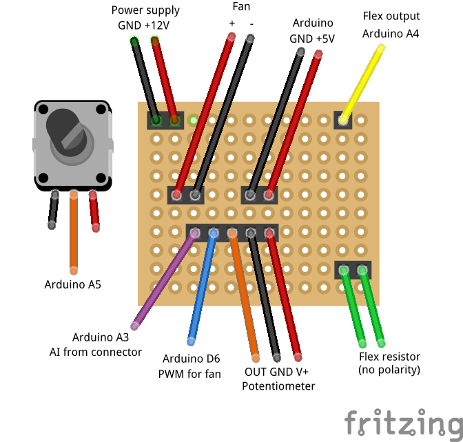
Connection
Flexy is contains small stripboard with pin headers to connect power supply, fan, sensor, and Arduino board. Wiring is described in the following image.
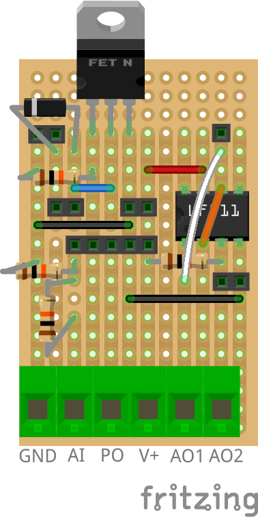
Individual electronic parts and and their layout on a stripboard is as follows.
Description of signal interface
The external connector can be used to hook up the Flexy to some other electronic device. This can be used either to control Flexy via some external controller (PLC, microcontroller, etc.) or for electrical debugging.
Connector (labeling from left-1 to right-6)
- GND* - common ground
- AI** - analog input (hooked to analog input of Arduino - A3 by default)
- Pot. out - output of potentiometer
- V+ - optional voltage supply for sensory circuit (use only if Arduino is not used/present in Flexy)
- AO1 - output of flex sensor (via impedance buffer - op-amp circuit)
- AO2 - output of flex sensor (via voltage divider)
* If external electronic device is connected to Flexy, ground terminals of both devices must be interconnected as well.
** Voltage provided on AI is passed through 10/10 kOhm voltage divider. Maximum acceptable voltage is 10V that is scaled down to 5V for Arduino analog input.
** AI terminal can be optionally used as a source of PWM for fan control. This can be done by putting a jumper over pins 1 and 2 of five-pin header terminal on stripboard. Recommended voltage level of PWM is 7-10V since the signal will be still passed through voltage divider.
Open-source materials